2.3 Data Analysis
- Analysis types
- Physical storage media analysis
- Volume analysis
- File System Analysis
- Application , OS analysis
- SWAP analysis
- Database Analysis
- Memory analysis
- Network analysis
2.2.4. General Guidelines
- Preservation - Isolation - Correlation - logging
- Preservation
- Copy important data to safe location.
- # values for integrity
- use of write blockers
- decrease no of interactions with the evidence.
- Isolation
- Isolate everything.
- Simple html file may have harmful javascript code.
- Correlate
- compare data with standard data to verification and standardization.
- Logging
- log everything.
2.2.3. Event Reconstruction Techniques
- Requires knowledge about OS and applications
- Aim of this phase is to create a hypothesis with supportive files, evidences etc
2.2.2 Evidence Searching Phase
- Varies case to case.
- Internet :- browser history , cache files , downloads
- OS :- presence of root kits , user accounts , installed software
- Know the case -> list possible areas/locations of contact -> investigate that areas/locations
- Search Techniques
- Name of the file
- Type of the file
- File related Timestamps
- #values in case of known files.
2.2.1 System Preservation Phase
- Trying to preserver the state of crime scene.
- Actions / methods are depending on
- Legal requirements
- Business requirements
- Operational requirements
- Ex. Easy case that may require seize the machine and clone the disk. Also there are some complicated cases like spyware etc.
- Few cases will not go to court (business , military )
- In preservation phase investigator tries to avoid overwriting the evidence.
Preservation Techniques
- Basic aim to to reduce tempering / overwriting.
- For dead analysis i)turn off the machine ii) start making copies
- For live analysis i) kill harmful processes ii) kill network if required iii)logging timestamps etc.
- #values for integrity
2.2 Digital Crime Scene Investigation Process
- There are THREE basic Phases
- System Preservation Phase
- Evidence Searching Phase
- Event Reconstruction Phase
###
Consider a traditional crime scene where someone got shot by bullets.
Will you allow people to walk over the scene? No because it damages the scene.
Will you stop working only after securing the scene? No, you will Search for useful evidence.
Will you stop after finding evidence ? No , you will try to reconstruct the event, guessing more details etc.
###
There are two types of investigations
- Dead investigation
- running trusted application in trusted OS.
- attaching seized pendrive to investigation workstation.
- Live investigation
- OS or other resources of the system are being investigated.
- investigating ongoing attack on the working server.
2.1 Digital Investigations and Evidence.
- Digital Investigation comes in a picture when
- Digital technology is used to break law. | Installation of hidden CCTV camera to violate privacy
- Digital property became target of criminal. | Hacking CCTV case
- Digital system might have witnessed a crime | CCTV footage
- Digital Investigation is a process to develop and test hypothesis that answer question about digital events
- Digital Evidence :- A digital device which contains reliable information that supports a specific event.
- Digital Forensic Investigation :- Use of Science and Technology to analyze a digital object to built a hypothesis
2.0. Digital Investigation Foundation
This is an informative chapter. We will not focus on technical points.
- Digital Investigations and Evidence.
- Digital Crime Scene Investigation Process.
- System Preservation Phase
- Preservation Techniques
- Evidence Searching Phase
- Search Techniques
- Event Reconstruction Techniques
- General Guidelines
- Data Analysis
- Analysis Types
- Essential and Non-essential data
- Overview of Toolkit
- EnCase
- FTK
- ProDiscover
- SMART
- The Sleuth Kit / Autopsy
1.3.3.5 SCSI Drives
- SCSI vs ATA
- ATA has either 40 or 44 pin connectors. SCSI has many types and shapes.
- ATA accommodates up to 2 devices, SCSI can accommodate more than 2.
- DEvices on SCSI cable needs unique numerical identifier , which can be done by either jumper or software.
- Few SCSI devices have Read-Only mode.
- SCSI has no controller. It is designed as a bus, where different devices can communicate with each other.
- Types of SCSI
- SCSI normal transfers 8 bit at a time , wide transfers 16 bits at a time.
- Single Ended method (SE), high voltage represents 1 and no voltage represents 0.
- Differential voltage method requires 2 wires for each bit. In case of 0 there is no difference, For 1 , one wire is set for +ve and another wire is set for opposite.
- Connector Types
- Single Connector Attachment. has power and data wires together.
- Size Barriers
- SCSI has no size barrier like ATA.
- if BIOS has some limitation , it may put some restrictions on storage capacity.
1.3.3.4 BIOS vs Direct Interface
- Direct Access to Controller
- Software should know how to interact with hard disk controller
- Software should know how about addressing and process of issuing command.
- BIOS Access to Controller
- Software does not have to know everything about controller.
- Entire communication is through BIOS.
1.1.3.3 Types of Sector Addresses
- Physical address is address of the sector with respect to start of physical media.
- One way of addressing was to mentioning plate number , track number and sector number called as CHS address.
- CHS is simple but not used anymore.
- ATA was using 16 bits,4 bits,8 bits for cylinder , Head and Sector respectively. Older BIOS uses 10 bits , 8 bits and 6 bits respectively.
- If ATA is connected with older BIOS, they can work with possible minimum value i.e. 10 bits, 4 bits, 6 bits so only 504 MB disks were compatible with the system.
- To overcome this 504 MB limit , special BIOS were developed to translate addresses from application to hard drive, But it did not support hard disk larger than 8.1 GB
- BIOS were not common, if uses and investigator uses different version of BIOS then no investigation was possible.
LBA (Logical Block Addressing)
- To overcome problems in previous section, LBA was introduced.
- Due to LBA software does not require to know about hard drive geometry.
- For backward compatibility , LBS to CHS formula is there
- LBA=((CYLINDER * Heads_Per_Cylinder) + HEAD) * SECTOR - 1
- Interface Standards
- ATA-1:- Supporting CHS & LBA.
- ATA-3 :- Self Monitoring Analysis and Reporting Technology. Supported Passwords
- ATA/ATAPI-4 :- 80 Wire cable. Supported HPA
- ATA/ATAPI-6 :- stopped supporting CHS.
- ATA/ATAPI-7 :-
- Disk Commands
- Controller issues commands on cable specifying disk (Master or Slave)
- Controller specifies what exactly he wants from the specific disk. Location of the data , read , write instructions etc
- Controller issues commands on cable specifying disk (Master or Slave)
- Controller specifies what exactly he wants from the specific disk. Location of the data , read , write instructions etc
- Hard Disk Passwords
- Optional, since ATA-3
- Can be set through BIOS or some other software.
- Two types of passwords Master and User.
- Master password was for company administrator in case user password is lost.
- High security mode:- Both password could unlock the disk.
- Maximum Security Mode :- User password to unlock, Master password to unlock only after wiping.
- HDD will require SECURITY_UNLOCK command with password.
- After no of unsuccessful attempts disk will freeze and rebooting was required.
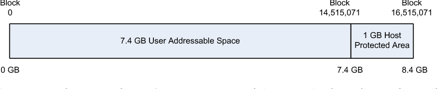
- Host Protected Area (HPA)
- Special area , generally unseen by common user. Can be configured by ATA.
- Invented with ATA-4.
- Computer vendor used to analysed it to detect whether disk is formatted by user or not
- READ_NATIVE_MAX_ADDRESS gives no all of available sectors.
- IDENTIFY_DEVICE gives no of accessible sectors
- the difference (if any) between commands mentioned in 4 ,5 is HPA, it was there but not seen by user
- To remove HPA
SET_MAX_ADDRESS should be executed with proper value
- Using SET_MAX_ADDRESS < READ_NATIVE_MAX_ADDRESS will create HPA.
- Special area , generally unseen by common user. Can be configured by ATA.
- Invented with ATA-4.
- Computer vendor used to analysed it to detect whether disk is formatted by user or not
- READ_NATIVE_MAX_ADDRESS gives no all of available sectors.
- IDENTIFY_DEVICE gives no of accessible sectors
- the difference (if any) between commands mentioned in 4 ,5 is HPA, it was there but not seen by user
- To remove HPA SET_MAX_ADDRESS should be executed with proper value
- Using SET_MAX_ADDRESS < READ_NATIVE_MAX_ADDRESS will create HPA.
- Device Configuration Overlay
- Since ATA-6
- DCO can be used to hide the data
- As we discussed , IDENTIFY_DEVICE command returns information about the device, DCO can be used to make IDENTIFY_DEVICE show smaller size.
- DEVICE_CONFIGURATION_SET used to create DCO
- DEVICE_CONFIGURATION_RESET used to remove DCO
- Serial ATA
- Solution for traditional ATA
- Traditional ATA cables were so big and rigid. Selecting master-slave by jumper was critical.
- Serial ATA, Only 1 bit information is transferred at a time as compare to 16 bit information in original or parallel ATA
- Jumpers are not required anymore
- Controller can be placed between computer and disk so that computer will not know the type of hard drive type (SATA or PATA)
1.1.3.2 ATA & IDE interface
- They have built in logic board.
- developed by
International Committee on Information Technology Standards (INCITS).
- Disk has controller which issues commands.
- Can be set either master or slave by changing jumper position.
1.1.3.1 Hard Disk Geometry & Internals
- Hard disk has one or more rotating plates. They are stacked on one on another. (Remember CD or DVD holder)
- Every plate is coated (sometime both sides) by magnetic material.
- Every plate is divided in number of circles called as track.
- For every coated surface of plate, there is a head to perform read and write operations.
- Track is divided in multiple sectors .It is the smallest addressable unit is known as a sector.
- In computer , numbering starts from 0. means if total no of objects are n then they are numbered from 0 to (n-1)
##Do not forget
Sector->track->plate or cylinder
## CHS Addressing
Room no 108 means 1st floor and 8th room. CHS is using similar method CHS (Cylinder, Head, Sector)
Address - Explanation
0,0,0 0th Cylinder - 0th track - 0th sector || in computer everything starts with 0
1,0,0 1st Cylinder - 0th track - 0th sector
1.1.3 Hard Disk Technology
Hard drive is one of the very common sources of digital evidence.
Understanding only file system is not enough. Understanding hard drive will make many things clear.
There are two types of hard drives AT Attachment(ATA/IDE) and Small Computer System Interface (SCSI)
1.1.2.2 Boot Code Location
Every Computer has BIOS (Basic Input Output System)
BIOS has ROM (Read-only Memory).
ROM has instructions to detect and configure devices.
After detecting storage device, CPU looks for the booting code.
##
Like you have the ability to search box full of books. |
You read the sticker on the box to know about books present in the box. | Selecting specific partition
based on that sticker you are deciding book to open | loading specific OS
##
Sometime we attach additional bootable device with OS, like Pendrive, CD,DVD etc and change boot sequence.
If your device has OS but the device is not bootable then it will be treated like regular data, that OS may not be booted.
1.1.2.1 CPU & Machine Codes
CPU
Central processing unit or processor. Can process assigned job. but cant create job for itself. OS assigns job to CPU. CPU picks up instructions from the memory.
1.1.2. Booting Process
When we start computer, operating system takes charge of hardware. But who does load the OS code from hard drive to processing ? This process is boot process.
1.1.1.5 Flag Values
Flag values represent certain status.
1. What does red traffic light suggest ?
2. What does glowing red light on operation room represent?
3. what does glowing break light of the vehicle represent ?
In computer flag takes one bit memory. It can store either 0 or 1. it means either True of flase.
for example device read only or not , device is being used or not, file is being used or not etc.
1.1.1.4 Data Structures
if data is not addressable then it is not accessible.
In library we have book register, It contains name of the book and location. Means certain book is present on given location (rack or cupboard)
On rack also some space is allotted to display identification of the rack (the same identification number is referred in register)
You can access the library easily if there is a proper way followed to organize books and you are aware with the same.
The same thing is implemented in computer. Computer knows from smallest addressable unit of the data , how much space is used for address and how much space is used to store actual data.
Use xxd command for more details
1.1.1.3 Strings and Encoding
How computer stores sentence ?
Computer does not know characters and symbols. Computer has a unique numerical value for a symbol.
Computer keep storing numerical values associated with the symbols.
For us its a sequence of character, but for computer its a sequence of numerical values
There are following major strategies
- ASCII:-
- Very simple.
- Limited number of symbols.
- Like 65 for A, 66 for B and so on.
- Sample ASCII table is here
- Unicode
- UTF32
- uses 4 bytes space for each character/symbol
- wastage of space
- UTF16
- 2 byte space for frequently used characters and for remaining 4 bytes
- economical as compared to UTF32.
- UTF08
- Uses 1,2,4 bytes for frequently used characters
- Bit difficult to process because variation in data size.
1.1.1.2 Data Sizes
Data Units
Smallest digital data unit is 'bit'. It can only store data but it has no space to store his own address / identification.group of 8 bit is known as 1 byte. further units are already well known.
Optimum use
Consider a page with capacity of writing 10 digits only. We need to put multiple pages together and make a book. Each page should have space for data and space for page number.
And length of data + length of page number =10 as stated before.
consider following cases
- 9 digits for data and 1 digit for page number:- here we are getting big space for data but very small space for page number i.e. address. So we can go for page no 0 to 9 (total 10). Even if we make a book, it will have maximum 10 pages only.
- 1 digit for data & 9 digits for page number:- in this case we can put 10^9 pages in book. but each page has capacity to store only 1 digit data.
Same thing happen with storage. If you want more number of data units , you have to spend more on addressing.
lower the address length, bigger but less in number the data units.
Addressing types
Big endian
This is in our general life example. we write most significant number to the left and least to the right.
Similarly most significant part of the data is written first then system writes least significant part.
"Is your cell no starts with 9405 ?"
Little endian
Here least significant part is written first then most significant part. You can say system writes data in reverse order.
"Is your cell no ends with 57?"
Both systems has there pros and cons as compare to each other.
1.1.1.1 Number systems
Number System
(Already covered in F.Y.)
Sample Example from our school days
1234=1000 + 200 + 30 + 4
=1*1000 + 2 * 100 + 3 * 10 + 4 * 1
=1 * 10^3 + 2 * 10 ^2 + 3 * 10^1 + 4 * 10^0
Why 10 is so important ? Why we are not skipping 10 with its power anywhere ? Why only 10 ?
The answer is we are using DECIMAL number system. it has 10 symbols 0 to 9, hence 10 is so important.
There are other number systems also like binary, octal , hexadecimal.
Binary
- Binary has 2 symbols (0 and 1).
- Any binary number will be composed of only 0 and 1. If you see other symbols in binary number then it is either mistake or its not a binary number.
- Like 10 in Decimal System, We will use 2 in binary number system to interpret the number
- 101 in binary = 1*2^2 + 0*2^1 +1*2^0
Octal
- Has 8 symbols (0 to 7).
- Any binary number will be composed of 0,1,2,3,4,5,6,7 (Not 8). If you see other symbols in Octal number then it is either mistake or its not an Octal number.
- Like 10 in Decimal System, We will use 8 in Octal number system to interpret the number
- 742 in binary = 7*8^2 + 4*8^1 +2*8^0
Hexadecimal
- Has 16 symbols (0 to 9 and A=10,B=11,C=12,D=13,E=14,F=15).
- Any Hexadecimal number will be composed of above symbols.
- Like 10 in Decimal System, We will use 16 in Hexadecimal number system to interpret the number
- 7BA in binary = 7*16^2 + 11*16^1 +10*16^0
Specifying Number system
We use decimal number system so we don't specify it. But in Computer Science using number without specifying number system is confusing for the reader.
Ex. 10 , it can be binary, octal ,decimal or hexadecimal
Ex. 12 , it can be octal, decimal or hexadecimal
Ex. 18 , it can be decimal or hexadecimal
To avoid such confusions we need to Specify number system as a subscript
2/b/B for Binary
8/o/O for Octal (try to avoid use of 'o' or 'O', it looks similar to '0')
10/d/D for Decimal
16/h/H for hexadecimal
1.1.1 Data Organization
The thing we are going to investigate is Digital Storage Device
It has nothing but the specially organized data.
There are different ways to organize same information.
1.0 Introduction
In this unit we will focusing on foundation.
Investigation part will not be covered in this unit.
- Computer Foundation
- We will learn how data is stored in storage devices
- What is booting process/ what happens when you start the computer/ how a particular OS takes charge of the hardware when we power on the machine
- Hard Disk technology, how hard disk works, different components of HDD
- Digital Investigation Foundation
- What are the useful evidences in digital investigation, what does make them eligible as a digital evidence
- Steps involved in investigation
- analysis of the acquired data
- Available tools for investigations
Subscribe to:
Comments (Atom)
-
Physical address is address of the sector with respect to start of physical media. One way of addressing was to mentioning plate number , tr...
-
CPU Central processing unit or processor. Can process assigned job. but cant create job for itself. OS assigns job to CPU. CPU picks up inst...
-
How computer stores sentence ? Computer does not know characters and symbols. Computer has a unique numerical value for a symbol. Computer k...
